I want to display the routing graph for the “foot” profile. I only changed the MiniGraphUI class to the “foot” profile.
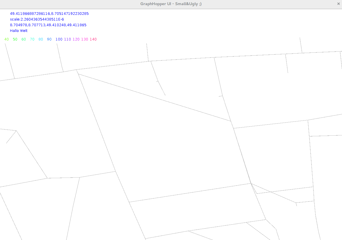
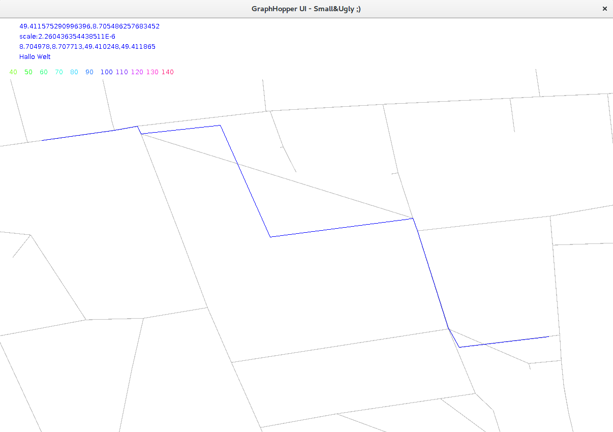
It seems that the MiniGraphUI does not show the real street network, but only displays the necessary nodes. However when I compute routes using the MiniGraphUI, it displays the correct routes how they would like in reality:
–
computed route:
I would like to display the “normal” street network - not any artificial shortcuts.
Does anyone have any idea how to do that?
Thanks and best regards!
This is a debugging tool showing you only the connection between junctions - ie. the underlying graph. To plot also the pillar nodes you can fetch and plot them via edge.fetchWayGeometry(2)
1 Like
Thanks. That was a good hint. I implemented it in this way:
while (edge.next()) {
g2.setColor(Color.GRAY);
PointList wayGeometry = edge.fetchWayGeometry(2);
int wayGeometrySize = wayGeometry.getSize();
if (wayGeometrySize > 1) {
    for (int i = 0; i < wayGeometrySize - 1; i++) {
        double lat_pillar_1 = wayGeometry.getLat(i),
                        lon_pillar_1 = wayGeometry.getLon(i);
        double lat_pillar_2 = wayGeometry.getLat(i + 1),
                        lon_pillar_2 = wayGeometry.getLon(i + 1);
        mg.plotEdge(g2, lat_pillar_1, lon_pillar_1, lat_pillar_2,
                        lon_pillar_2, 1.2f);
    }

} else {
    int nodeId = edge.getAdjNode();
    int sum = nodeIndex + nodeId;
    if (fastPaint) {
        if (bitset.contains(sum))
            continue;
        bitset.add(sum);
    }

    double lat2 = na.getLatitude(nodeId);
    double lon2 = na.getLongitude(nodeId);
    mg.plotEdge(g2, lat, lon, lat2, lon2, 1.2f);
}
}
It works for me so far. But I am sure there is a much nicer way how to do it …